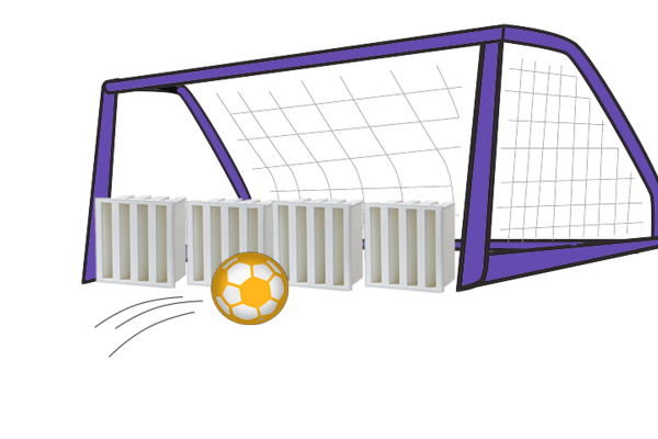
No, we are not talking about football, we are talking about filter houses! According to our market research, a large number of filter houses worldwide are equipped with round pulse filters. And we ask ourselves: Why is that?

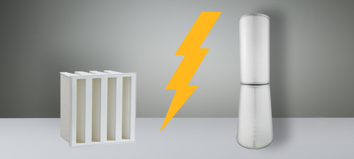
For decades, EMW® has resisted manufacturing pulse filters - until now! For the purpose of comparison between cartridge filters and compact filters, we have manufactured a pulse filter with the dimensions 352/240 x 900 (OD/ID x L) with a synthetic medium of filter class ISO ePM1 80 % according to ISO 16890 (formerly F9 according to EN 779). Not just any pulse filter - the pleat pack was not manufactured with the usual pleat-lock technology, but in mini-pleat design with hot melt spacers. The pressure difference measured on this pulse filter at a volume flow of 1500 m³/h is 140 Pa. This is a respectable value compared to the result on the filters of some of our market competitors, which usually have an initial pressure difference of around 170 Pa at the same volume flow.
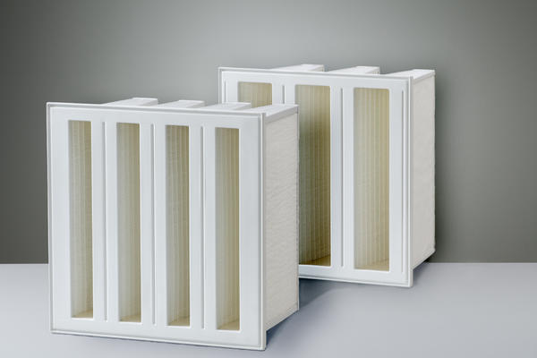
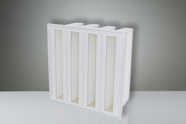
This paper, however, is not about a comparison with our competitors, but a comparison with EMW®'s own compact filter of the MPK 49-20 series. We have not only equipped this compact filter with the same medium as the pulse filter, it is even the same batch, even the same media roll. One and the same medium - 2 different types of filters!
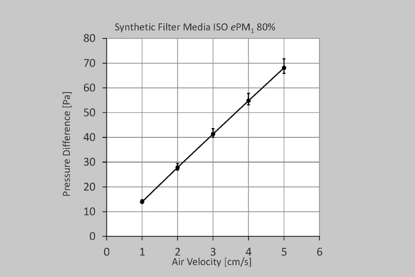
The pressure difference of a filter results from its aerodynamic design and the medium used. Let us first consider the medium. The diagram on the rigth shows a typical pressure difference curve of the medium used in its flat design. This means that the medium was not tested for its pressure loss in a folded version, but as a flat product at different inflow velocities.
Unlike what you may be used to, the pressure difference in the diagram is not plotted against the volume flow in m³/h, but against the flow velocity in cm/s, which results with the area of the tested media samples. The result is a linear characteristic.
So far, so good - we know that does not help you very much now. Let us now compare the pressure differences that result at the pulse filter and the compact filter. The pulse filter was tested up to a test volume flow of 1500 m³/h, which is distributed over 20.5 m² effective filter area. The 17.8 m² effective filter surface of the compact filter was tested up to a test volume flow of 3400 m³/h. At first glance, it is noticeable that the effective filter areas are approximately on a comparable level, whereas the volume flows differ greatly. The picture becomes clearer if the pressure loss, as before with the flat medium, is also related to the air velocity for the prefabricated filters in relation to the flowable area of the medium in the filters. Accordingly, the filter medium in the pulse filter is flowed through at 2.03 cm/s, while the filter medium of the compact filter is flowed through at 5.31 cm/s. We have worked out the whole thing graphically for you:
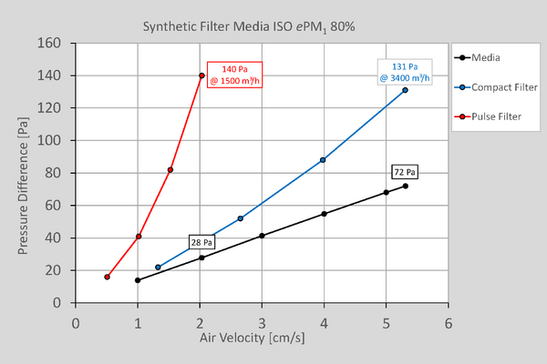
The graph shows the pressure difference curve of the medium up to 5.31 cm/s, of the compact filter also up to 5.31 cm/s (corresponds to 3400 m³/h) and of the pulse filter up to 2.03 cm/s (corresponds to 1500 m³/h). At an inflow velocity of 2.03 cm/s, the medium has a pressure difference of 28 Pa, whereas the pulse filter has a pressure difference of 140 Pa. In the compact filter, the pressure difference of the filter is 131 Pa and of the medium 72 Pa @ 5.31 cm/s. The difference between the pulse filter and the medium of 140 - 28 = 112 Pa, as well as the compact filter of 131 - 72 = 59 Pa results from the aerodynamic design of the respective filter and the pleat geometry of the pleat pack(s).
As an interim result we can state: The negative influence of the aerodynamic design of the pulse filter including pleat pack is 112 Pa higher, than that of the compact filter with 59 Pa.
Knowing, you as a specialist in filtration, you will certainly have noticed that this comparison is once again comparing apples with oranges. The medium in the pulse filter only flows at 2.03 cm/s, whereas the compact filter is confronted with 5.31 cm/s. That is more than 2 ½ times the speed. We have therefore taken the liberty of creating comparable conditions. In the following graphs you can see how the pressure differences on the plane medium, on the pulse filter and on the compact filter appear at the same air velocities.

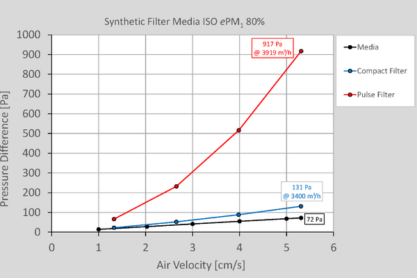
At 2.03 cm/s, the medium has a pressure difference of 28 Pa, the compact filter of 37 Pa and the pulse filter of 140 Pa. This velocity corresponds to a volume flow of 1301 m³/h for the compact filter. At 5.31 cm/s, the plane medium has a pressure difference of 72 Pa, the compact filter of 131 Pa and the pulse filter of an incredible 917 Pa. The volume flow of the pulse filter corresponds to 3919 m³/h if its filter medium were to flow at the same speed as the compact filter. The negative influence of the aerodynamic design of the pulse filter including the pleat pack is now 917 - 72 = 845 Pa compared to that of the compact filter with 131 - 72 = 59 Pa.
It should be noted here that on the market more filter surface is usually put into a comparable pulse filter to our prototype, which further reduces the air velocity of the medium. Theoretically, the pressure difference of a comparable pulse filter should also be lower, which is often not the case in practice. Here, in case of doubt, the aerodynamics or pleat geometry were not sufficiently considered.
Practical example GT26

Where does this disparity between the different types of static air filters and pulse filters come from? One indication is the operating volume flow for the application. For the specific air filters, we have chosen a special gas turbine machine type in which both of these filters are used - an Alstom GT26. This machine creates a volume flow of 518 m³/s or 1,864,800 m ³/h.1 In a specific plant in Europe, this volume flow is distributed over 518 static compact filters, in the Middle East over 1176 pulse filters. This results in an operating volume flow of 3600 m ³/h for the compact filters and about 1585 m ³/h for the pulse filtration. This shows that the negative influence of the aerodynamic design of the pulse filter including the pleat pack must necessarily be compensated by the number of filters used in order to be able to operate the pulse filters at a tolerable pressure difference level.
1 F. Muscroft (2006) Gas Turbine Combustion Air Its Effects,
Treatment And Operational costs, p. 76
But where does the design of the filter house for a certain operating volume flow per filter element come from?
We cannot say exactly! Probably the reason is that in the past, filter house construction and filter manufacture of compact filters were not in one hand. The filter house builder asked the filter manufacturer to specify his compact filters, who provided proof of the quality class with an EN 779 (today: ISO 16890) test certificate. Both standards set the test volume flow to 3400 m³/h in case of doubt. In contrast, filter house construction and filter production of a pulse filtration system were historically in the hands of one manufacturer for a long time. The manufacturer of the filter house, including the air filters, was free to choose the operating volume flow for the filter elements, especially because there was explicitly no test specification for pulse filters available on the market and thus no test volume flow was "specified". On the contrary, the Saudi Aramco DeskTop Standards, which describe a system test of cleanable filter systems, even define that the initial pressure difference of the system must not exceed 400 Pa and describe that the usual velocity of the medium for so-called TTD filter types is 1.5 cm/s. This means that everything is done here to ensure that the test volume flow for the filter elements does not exceed 400 Pa. Here, everything is done to keep the velocities of the pulse filter at the lowest possible level.
Why this should not apply to static compact filters and thus create an unequal performance picture on the market if the influencing variables are not included in the analysis is still not apparent to us.
To resume the football jargon mentioned at the beginning, static GT compact filters form a solid defence to safeguard power plant operations even in the face of high waves of offense by the most diverse condensed formations.